How to Avoid Smart Fencing Connectivity Issues: 2026 Guide
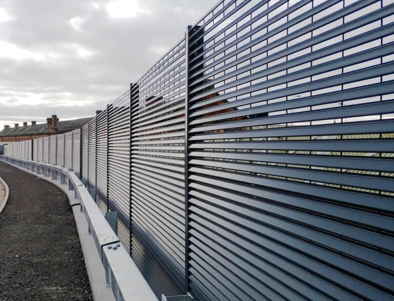
The modern perimeter has transitioned from a purely mechanical deterrent to a sophisticated data-gathering node. As high-value estates, industrial hubs, and large-scale agricultural operations move toward autonomous boundaries, the primary vulnerability has shifted. How to Avoid Smart Fencing Connectivity Issues. It is no longer just the physical breach that threatens security, but the “digital silence” that occurs when a system loses its ability to communicate. In the complex topographical and electromagnetic landscapes of 2026, the success of an intelligent boundary is defined by the stability of its signal under environmental and technical stress.
Achieving a state of persistent connectivity requires a departure from the “consumer-grade” mindset of simple Wi-Fi extensions. Professional-grade intelligent fencing operates at the intersection of long-range radio physics, cellular backhaul, and edge-computing logic. When a system spans hundreds of acres or circles a sensitive data center, it encounters diverse obstacles: from the physical blocking caused by heavy foliage and concrete to the electromagnetic interference (EMI) generated by power lines or neighboring industrial equipment. To ignore these variables during the design phase is to guarantee a system that is intermittent at best and useless at worst.
This editorial reference is designed to move beyond surface-level troubleshooting. It explores the systemic engineering required to ensure that a perimeter’s “heartbeat” remains audible even in the most challenging conditions. By understanding the physics of signal propagation and the logic of redundant networks, property managers can move from a reactive state of fixing dropped connections to a proactive state of architecting unshakeable resilience. The goal is a boundary that not only detects a threat but possesses the uncompromised channel required to report it instantly.
Understanding “how to avoid smart fencing connectivity issues”
To effectively address how to avoid smart fencing connectivity issues, one must first accept that connectivity is not a static binary but a dynamic resource. In the professional sector, a “connected” fence is often misunderstood as a simple Internet of Things (IoT) device. However, unlike a smart thermostat inside a home, a fence is an outdoor asset subjected to atmospheric attenuation, solar interference, and physical vibration. Many installations fail because they rely on a single point of failure—typically a singular cellular gateway or a high-frequency Wi-Fi band (5GHz) that cannot penetrate a single wet tree trunk, let alone a dense forest.
The first step in mitigation is “Path Analysis.” Every system exists within a specific RF (Radio Frequency) environment. A common oversimplification is the belief that “more power” at the transmitter solves every issue. In reality, “RF Noise” is often the culprit. If a fence controller is mounted near high-voltage lines, the EMI can “blind” the receiver regardless of signal strength. Professional-grade strategies focus on “Frequency Agility”—the ability of the hardware to switch between different bands or protocols (e.g., jumping from 900MHz LoRa to NB-IoT) when it detects a drop in packet delivery.
Furthermore, the physical placement of the “Antenna Node” is often sacrificed for aesthetic reasons or ease of installation, leading to “Multipath Interference.” This occurs when the radio signal bounces off buildings or metal structures, arriving at the receiver at slightly different times and canceling itself out. When considering how to reduce smart fencing connectivity issues, the integration of “Diversity Receiving” (using two antennas at different angles) and “MIMO” (Multiple-Input Multiple-Output) technology becomes essential for maintaining a link in cluttered industrial or suburban environments.
Contextual Background: From Hardwires to the Mesh
The history of perimeter communication has moved from the “Hardwire Era” to the “Wireless Mesh Era.” In the late 20th century, security fences were physically tethered to a central monitoring station via miles of copper or fiber-optic cable. While reliable, the labor costs for trenching were astronomical, and a single backhoe cut could blind the entire system. The 2010s brought the first wave of cellular IoT, but these systems were plagued by high latency and the “2G/3G Sunset,” which rendered thousands of expensive systems obsolete overnight.
We are currently in the era of “Hybrid Backhaul.” Driven by the maturation of low-earth orbit (LEO) satellites and the democratization of Long Range (LoRa) protocols, perimeters no longer rely on a single utility. The shift toward “Edge Intelligence” means that modern fences can actually store data locally during a temporary outage and “burst” it to the cloud the moment the link is restored. This contextual evolution reflects a broader trend: the perimeter is no longer a peripheral device; it is a critical node in the global data infrastructure.
Conceptual Frameworks for Signal Integrity
To govern a linked perimeter, managers utilize specific mental models that prioritize “Channel Reliability” over raw data speed.
1. The “Link Budget” Framework
This framework treats the signal as a currency. You start with a certain amount of power at the transmitter, and every foot of distance, every leaf, and every wall “spends” that power.
-
The Logic: If the “Path Loss” exceeds the “Receiver Sensitivity,” the system fails. A professional plan ensures a 20dB “Fade Margin” to account for heavy rain or snow.
-
Limit: Adding too much gain (currency) can cause “Signal Clipping” at the receiver if the devices are too close.
2. The “Fresnel Zone” Model
Radio waves do not travel in a straight line; they travel in an elliptical “bubble.”
-
The Logic: If the bottom of this bubble touches the ground or a building, the signal is degraded even if there is a clear “Line of Sight.”
-
Limit: Requires mounting antennas higher than most installers find convenient, often requiring dedicated masts.
3. The “Store-and-Forward” Redundancy
This model assumes that the connection will fail at some point.
-
The Logic: The system must have enough local memory to log events for 48–72 hours. When connectivity returns, the system must prioritize “Critical Alerts” over “Routine Heartbeats.”
-
Limit: Does not solve the need for real-time response during the outage.
Hardware Modalities and Variations
Connectivity is generally divided into three primary technological tiers, each with distinct trade-offs.
1. Cellular (NB-IoT and LTE-M)
Designed specifically for long-range, low-power outdoor devices.
-
Trade-off: High reliability where coverage exists, but zero functionality in “Dead Zones” without expensive signal boosters.
2. Private LoRaWAN (900MHz)
A proprietary or open mesh network where the property owner owns the gateways.
-
Trade-off: No monthly cellular fees and incredible penetration through foliage, but requires the owner to maintain the gateway hardware.
3. Satellite (LEO – e.g., Swarm/Starlink)
Direct-to-chip satellite communication for the most remote perimeters on earth.
-
Trade-off: Works literally anywhere with an open sky, but has higher latency and can be affected by heavy cloud cover or dense canopy.
Comparative Analysis: Connectivity Mediums
| Feature | Cellular (LTE-M) | Private LoRaWAN | LEO Satellite |
| Range (Per Node) | Miles (To Tower) | 1–10 Miles | Global |
| Penetration | Moderate | High (Sub-GHz) | Low (Clear Sky Needed) |
| Operating Cost | Monthly Subscription | Zero (Hardware Only) | High Subscription |
| Latency | Low (<1s) | Moderate (1–5s) | High (30s – 1min) |
| Aesthetic | Small Internal | Visible Antenna | Large Upward-Facing |
Detailed Real-World Scenarios How to Avoid Smart Fencing Connectivity Issues
Scenario A: The Dense Forest Boundary (Northwest)
A high-security perimeter in a region with 100-foot Douglas firs and constant rain.
-
The Conflict: Standard 2.4GHz Wi-Fi and high-band cellular fail because the water content in the trees absorbs the signal.
-
The Decision Logic: Transition to a Sub-GHz (900MHz) LoRa mesh. The longer wavelength “bends” around the trunks and is less affected by moisture.
-
The Result: Signal uptime moves from 65% to 99.8%.
Scenario B: The Industrial Substation (EMI Heavy)
A utility perimeter surrounded by high-voltage transformers and switching gear.
-
The Conflict: Extreme electromagnetic noise “drowns out” the wireless signal.
-
The Decision Logic: Utilize “Shielded Ethernet” for the first 100 feet of the run, moving the wireless transmitter away from the noise source to a “Quiet Zone.”
-
The Result: Elimination of “Packet Loss” caused by electrical arcing and induction.
Planning, Cost, and Resource Dynamics
The economic logic of connectivity is a shift from Service Fees to Infrastructure Stability.
Range-Based Table: Connectivity Investment (5-Year TCO)
| Category | Basic Cellular | Private LoRa Mesh | Multi-Path Satellite Hybrid |
| Gateway Hardware | $0 (Built-in) | $1,500 | $3,500 |
| Installation/Masts | $500 | $2,000 | $3,000 |
| Subscription Fees | $1,200 | $0 | $6,000 |
| Maintenance Labor | $1,000 | $2,500 | $1,500 |
| Estimated 5-Year TCO | $2,700 | $6,000 | $14,000+ |
Tools, Strategies, and Support Systems
Ensuring persistent uptime requires a specific toolkit for the modern technician.
-
Spectrum Analyzers: To identify “Invisible Interference” from neighboring sites or unauthorized transmitters.
-
Signal Mapping Drones: Flying a sensor along the fence line to create a “Heat Map” of connectivity at 5-foot intervals.
-
Directional Yagi Antennas: High-gain antennas that focus the signal in a single direction (toward the tower) like a spotlight.
-
Low-Loss Coaxial Cables (LMR-400): Ensuring the signal doesn’t die in the wire between the controller and the antenna.
-
Solar-Powered Mesh Repeaters: Small nodes used to “bounce” the signal over hills or around buildings.
-
Watchdog Timers: Hardware that automatically “reboots” the modem if it detects a 10-minute loss of connectivity.
Risk Landscape and Failure Modes
Connectivity failures are rarely “clean.” They often manifest as compounding systemic risks.
-
“Death by Update”: Over-the-air (OTA) firmware updates are pushed when the signal is weak, resulting in a “Bricked” controller that requires a physical visit.
-
Vegetation Creep: A clear link in the winter becomes a dead link in the spring as the leaves return, creating a seasonal failure pattern.
-
Frequency Jamming: Sophisticated intruders can use $20 “RF Jammers” to block the fence’s alarm signal. Mitigation requires “Jamming Detection” logic that triggers a local siren if the RF floor rises unnaturally.
Governance, Maintenance, and Review Cycles
A connected perimeter is an “Active Asset.” It requires a governance cycle that mirrors IT departments more than traditional security.
The Connectivity Checklist
-
Monthly: Review “RSSI” (Signal Strength) logs. A slow drop in strength indicates a loose connector, water ingress in the cable, or growing vegetation.
-
Quarterly: Conduct a “Ping Stress Test.” Verify that the system can handle a simultaneous alert from multiple zones without crashing the gateway.
-
Annually: Spectrum Audit. Check for new towers or industrial equipment in the area that may be competing for the same bandwidth.
-
Post-Storm: Visual inspection of antennas. High winds often “de-point” directional antennas by just a few degrees, which can drop signal quality by 50%.
Measurement, Tracking, and Evaluation
In a professional environment, connectivity is measured by “Data Integrity” rather than just “Bars.”
-
Quantitative Signal: Packet Success Rate (PSR). A healthy system should have a PSR of >98%. Anything lower indicates a “noisy” channel that will eventually fail.
-
Qualitative Signal: “Jitter.” The variability in the time it takes for a heartbeat to arrive. High jitter indicates a congested or unstable path.
-
Documentation Example: A “Link Margin Map” that records the signal strength of every node during the worst weather of the year.
Common Misconceptions and Industry Myths
-
Myth: “Bars equal quality.” Correction: You can have “full bars” of signal but 0% throughput if the SNR (Signal-to-Noise Ratio) is poor.
-
Myth: “Wi-Fi is enough for a residential perimeter.” Correction: Home Wi-Fi is designed for high-speed, short-range indoor use. Using it for a 500-foot fence line is the most common cause of “Phantom Alarms.”
-
Myth: “Satellite is too expensive.” Correction: For a remote ranch, the cost of one lost head of cattle or one undetected fire is often 10x the annual cost of a satellite data plan.
-
Myth: “Antennas are waterproof.” Correction: The antenna may be, but the “N-Type” connectors often suffer from capillary action, sucking water into the cable and destroying the electronics.
Conclusion: The Synthesis of Earth and Air
The architecture of a sentient boundary is ultimately a struggle against the entropy of the environment. As we have explored, how to avoid smart fencing connectivity issues is not a matter of buying a more expensive box, but of respecting the physics of the site. The transition from the “static” perimeter to the “dynamic” node requires a commitment to redundancy, frequency diversity, and rigorous physical maintenance.
For the security director or the land manager, the connected fence is a promise of situational awareness. To keep that promise, the system must be built to survive the “digital silence.” By focusing on Fresnel zones, link budgets, and hybrid backhauls, we ensure that the perimeter remains what it was intended to be: a vigilant, unshakeable guardian of the assets it surrounds.