How to Manage Smart Fencing Signal Loss: A Definitive Guide
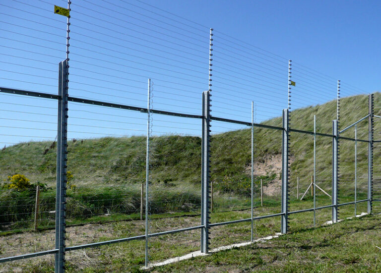
The shift from physical containment to intelligent, networked boundaries has introduced a paradox into modern property management. While “smart” fencing—whether through GPS geofencing, radio-frequency (RF) induction, or IoT-enabled physical barriers—offers unprecedented flexibility and data-rich monitoring, it replaces the mechanical certainty of a wooden post with the invisible volatility of electromagnetic waves. When a physical fence fails, the breach is visible to the naked eye. How to Manage Smart Fencing Signal Loss. When a smart fence fails, the boundary often vanishes silently into the background noise of the ionosphere or a congested local network.
This transition requires a fundamental shift in the operator’s mindset. Managing a smart perimeter is no longer a task for a carpenter, but for a systems administrator. The primary adversary is no longer rot or physical impact, but “signal loss”—a broad term encompassing everything from GPS drift and RF interference to the total “blackout” of a cellular backhaul. Understanding the physics of how these signals propagate, attenuate, and fail is the first step toward building a resilient containment strategy. Without this technical grounding, a smart fence is merely a psychological comfort that exists only as long as the weather is clear and the batteries are charged.
Addressing signal degradation is not a matter of finding a single “fix.” It is an exercise in layered redundancy. For the agriculturalist managing thousands of acres of livestock, or the estate owner securing a high-value perimeter, the goal is “graceful degradation.” This means designing a system that does not catastrophically fail when a signal drops, but instead transitions to a secondary mode of containment or provides an immediate, high-priority alert to the human operator. In the following sections, we will deconstruct the architecture of signal resilience and provide an editorial roadmap for maintaining perimeter integrity in an increasingly noisy digital world.
How to Manage Smart Fencing Signal Loss
To effectively address how to manage smart fencing signal loss, one must first dismantle the oversimplification that “loss” is a binary state. In a professional context, signal loss exists on a spectrum of degradation. A system may have “locked” onto enough satellites to provide a location, but if the Horizontal Dilution of Precision (HDOP) is high, the “smart” fence has effectively shifted several meters from its intended coordinate. This is not a total loss, but a “drift” failure that can lead to unintended corrections or unmonitored gaps.
Managing this complexity requires a multi-perspective approach. From a hardware standpoint, it involves selecting frequencies that penetrate foliage or terrain effectively. From a software perspective, it involves “dead reckoning” algorithms that use internal gyroscopes to predict a subject’s position when the primary signal vanishes. A common misunderstanding among users is that a “strong signal” on a mobile device equates to a stable fence. In reality, the low-power receivers used in fencing collars or sensors are far more sensitive to “multipath interference”—where signals bounce off metal sheds or wet leaves—than a standard smartphone.
The risk of oversimplification often leads to a “set it and forget it” installation. A robust management plan recognizes that the environment is dynamic. A fence that works perfectly in the winter may fail in the spring as trees leaf out and block line-of-sight to the horizon. Therefore, the strategy must be proactive: identifying “dead-zones” through signal heat-mapping before they lead to a breach, and establishing clear protocols for what the system should do when the signal-to-noise ratio drops below a critical threshold.
Deep Contextual Background: The Physics of Exclusion
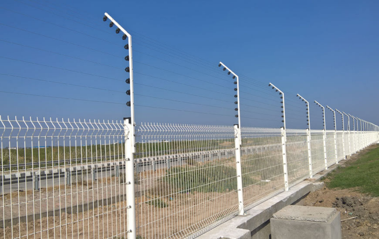
The history of fencing has always been a battle against entropy. For centuries, this was physical entropy—wood rotting or wire rusting. The “smart” revolution shifted this to electromagnetic entropy. The earliest invisible fences utilized buried copper wires that acted as low-frequency antennas. Signal loss in these systems was usually caused by a physical break in the wire (induction failure). The move toward wireless systems—first RF and later GNSS (GPS)—removed the wire but introduced a host of environmental variables that were previously irrelevant.
As we move toward 2026 and beyond, the systemic evolution is defined by “spectrum congestion.” With the proliferation of IoT devices, 5G networks, and even Starlink-style satellite arrays, the background noise of the atmosphere is increasing. Modern smart fencing must now “compete” for clarity. This contextual background is vital because it explains why “legacy” wireless fences often fail in modern suburban environments; they were designed for a world with significantly less RF interference. Today’s management strategies must account for a crowded sky.
Conceptual Frameworks and Mental Models
When engineers and sophisticated estate managers analyze signal stability, they rely on several core frameworks to ensure the boundary remains “logical” even when the physical signal is weak.
1. The Signal-to-Containment Ratio
This model suggests that the reliability of the fence is directly proportional to the “fidelity” of the location data. If a signal drops by 30%, the physical containment area must effectively “shrink” its warning zones to prevent accidental corrections.
-
Limit: This framework assumes the subject (animal or intruder) is trained. It cannot compensate for a subject that realizes the “invisible wall” is flickering.
2. The Defensive Layering Model (Redundancy)
A smart fence should never rely on a single frequency.
-
Layer 1: GPS for broad geofencing.
-
Layer 2: Local RF beacons for high-precision zones (e.g., near a gate).
-
Layer 3: Inertial Measurement Units (IMU) for short-term “dead reckoning.”
-
Limit: Increased layering leads to higher battery consumption and technical complexity.
3. The “Fail-Secure” vs. “Fail-Static” Logic
This mental model forces a decision on what the receiver should do during total signal loss.
-
Fail-Secure: The receiver issues a warning if it loses signal, forcing the subject back into the center of the yard.
-
Fail-Static: The receiver goes dormant to prevent “ghost corrections,” but leaves the perimeter open.
-
Limit: Fail-secure can cause “boundary fear” if the signal drops while the subject is in a safe area.
Hardware Categories and Signal Modalities
Different smart fencing hardwares handle signal loss in varying ways. Selecting the right modality is the first step in long-term management.
1. GNSS / GPS Geofencing
Relies on a constellation of satellites.
-
Signal Vulnerability: Atmospheric conditions, “urban canyons” (tall buildings), and dense canopy cover.
-
Management: Requires high-quality antennas and “dual-band” receivers (L1/L5) to filter out multipath interference.
2. Radio Frequency (RF) Circular Hubs
A central transmitter creates a radio “bubble.”
-
Signal Vulnerability: Metal siding, large mirrors, and terrain changes (hills block RF).
-
Management: Strategic placement of the hub in a high, central location with clear line-of-sight.
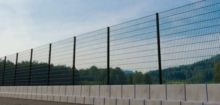
3. IoT-Enabled Mesh Networks
Physical fences with vibration sensors that report back via LoRaWAN or Zigbee.
-
Signal Vulnerability: Distance from the gateway and interference from other 2.4GHz devices.
-
Management: Use of repeaters or high-gain directional antennas to ensure every sensor has a “path” home.
4. Ultra-Wideband (UWB) Beacons
High-precision, short-range pulses.
-
Signal Vulnerability: Very short range; requires a “dense” installation of beacons.
-
Management: Primarily used for small, high-value “keep-out” zones (e.g., swimming pools).
Comparative Analysis: Signal Resilience by Modality
| Modality | Signal Range | Primary Obstacle | Stability in Storms | Complexity of Fix |
| GPS | Unlimited | Tree Canopy | Moderate | Software/Antenna |
| RF Hub | ~200 ft | Metal Siding | High | Hub Relocation |
| LoRaWAN | ~5-10 Miles | Terrain/Hills | Very High | Adding Repeaters |
| Bluetooth/Wi-Fi | ~50-100 ft | Everything | Low | N/A (Limited Use) |
Real-World Scenarios and Failure Modes How to Manage Smart Fencing Signal Loss
Understanding how to manage smart fencing signal loss is best illustrated through the lens of specific environmental constraints.
Scenario A: The “Leaf-Out” Failure
A rural property utilizes GPS fencing for livestock. In winter, the system is 99% accurate. In June, the dense oak canopy fills in.
-
Failure: The HDOP (Dilution of Precision) rises, and the “boundary” begins to wobble by 15 feet.
-
Management Decision: The operator must manually expand the “Safe Zone” in the app or install an outdoor GPS repeater to strengthen the satellite lock under the canopy.
Scenario B: The Solar Flare “Ghost”
A high-intensity solar storm disrupts the ionosphere, causing GPS signals to delay as they pass through the atmosphere.
-
Failure: The receivers report a position that is 30 meters off. The animals receive corrections while standing at the water trough.
-
Management Decision: The system should have an automated “Solar Weather” lockout that disables corrections when satellite integrity is compromised globally.
Scenario C: The Urban Radio Congestion
A smart fence in a dense suburban neighborhood near a municipal radio tower.
-
Failure: The RF signal is “drowned out” by the sheer volume of 900MHz traffic.
-
Management Decision: Switching to a FHSS (Frequency Hopping Spread Spectrum) hardware that can “jump” between channels to find a clear path.
Planning, Cost, and Resource Dynamics
Resilience is not free. When planning a smart perimeter, the “redundancy budget” is often as large as the initial hardware cost.
Direct and Indirect Costs
-
Redundant Hardware: Adding a secondary LoRaWAN gateway or outdoor antennas ($200–$800).
-
Calibration Labor: Time spent walking the perimeter with a signal meter to map “dead zones” (10–20 hours/year).
-
Opportunity Cost: The risk of an animal escaping or an intruder entering during a signal blackout.
Estimated Investment for Signal Stability
| Component | Standard Entry Level | Professional Resilient | Enterprise/Industrial |
| Primary Hardware | $400 | $1,200 | $5,000+ |
| Signal Repeaters | N/A | $300 | $1,500 |
| Backup Power (UPS) | N/A | $150 | $1,000 |
| Yearly Maintenance | $0 | $200 (Software) | $1,000 (Audits) |
| Total TCO (3yr) | $400 | $2,250 | $9,500+ |
Tools, Strategies, and Support Systems
To maintain a high-fidelity signal, several “support” technologies are essential.
-
GNSS Signal Repeaters: Devices that capture satellite signals from an open area and rebroadcast them into “shadowed” areas (under barn eaves or dense trees).
-
Faraday Shielding (Awareness): Recognizing that metal structures are signal killers and either moving hubs away from them or using external antennas.
-
Spectrum Analyzers: Low-cost handheld devices used to see “invisible” noise on 900MHz or 2.4GHz bands.
-
Battery Management Systems (BMS): Ensuring that a low-battery state doesn’t lead to “low-voltage signal drift.”
-
Offline Map Caching: Ensuring the system doesn’t fail just because the cellular data (internet) connection to the central server is lost.
-
Inertial Dead Reckoning: Using on-board accelerometers to “guess” location for 30–60 seconds after a GPS signal is lost.
Governance, Maintenance, and Signal Auditing
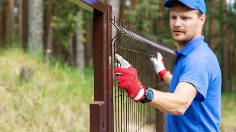
A smart fence is not a “install once” asset. It requires a governance cycle to ensure that environmental changes don’t erode the boundary.
The Signal Audit Checklist
-
Monthly: Check the firmware status. Manufacturers often release patches to improve signal processing logic.
-
Quarterly: Perform a “Boundary Walk.” Take a receiver collar and walk the perimeter to ensure the “Warning Tone” still triggers at the correct physical markers.
-
Seasonally: Recalibrate for foliage changes. What worked in the winter may need “Buffer Expansion” in the summer.
-
Post-Storm: Inspect outdoor gateways and antennas for physical shifting or moisture ingress in the connectors.
Adjustment Triggers
-
If the “Nuisance Alarm Rate” (false corrections) increases by more than 10% in a week.
-
If any new metal structure (shed, silo, vehicle) is moved within 50 feet of the RF hub.
-
If a neighbor installs a high-power Wi-Fi mesh system nearby.
Measurement, Tracking, and Evaluation
You cannot manage what you do not measure. A definitive smart fence plan must track signal health as a primary KPI.
Leading Indicators (Predictive)
-
Average Satellite Count: If the receivers are consistently seeing fewer than 8 satellites, the system is at high risk of drift.
-
Signal-to-Noise Ratio (SNR): A drop in SNR indicates increasing interference from other devices.
-
Battery Cycle Stability: Fluctuating voltages can cause sensor inaccuracy.
Lagging Indicators (Retrospective)
-
Breach Frequency: How many times did the subject cross the line?
-
Signal Recovery Time: How long does it take for the system to “re-acquire” a lock after moving out of a dead-zone?
-
Operator Overrides: How many times did a human have to manually reset the system?
Documentation Example: The Signal Log
| Date | Zone | SNR | Satellite Count | Issue | Resolution |
| Mar 12 | North Woods | 12dB | 4 | Heavy Rain/Canopy | Added GPS Repeater |
| Mar 15 | Barn Gate | 35dB | 12 | None | Baseline Established |
Common Misconceptions and Oversimplifications
-
Myth: “Cloudy days cause signal loss.” Correction: Clouds have almost no impact on GPS/RF signals. The primary culprit is “water-laden foliage” (wet leaves) and heavy moisture in the soil, which absorb RF energy.
-
Myth: “More satellites mean more accuracy.” Correction: Geometry matters more than count. Four satellites spread across the sky provide a better “fix” than ten satellites clustered in one corner.
-
Myth: “Wireless fences are ‘no maintenance’.” Correction: They are “no physical labor” fences, but they require significant “digital labor” to maintain calibration.
-
Myth: “Cellular signal and GPS signal are the same.” Correction: They are completely different frequencies and technologies. You can have 5 bars of cell service and zero GPS lock.
-
Myth: “Metal doesn’t block GPS.” Correction: Even a thin aluminum roof will completely kill a GPS signal. Smart collars must have a clear “view” of the sky.
Ethical and Practical Considerations
The management of signal loss carries an ethical weight. If an animal is contained by a smart system and that system fails, the animal may be corrected unfairly or wander into a dangerous area (e.g., a highway). Therefore, the “smartest” part of the fence should be its honesty. A system that knows it is “blind” and refuses to issue a correction is more ethical than one that “guesses” and shocks the animal for standing in the wrong place. Property owners must weigh the practical convenience of an invisible fence against the moral obligation to provide a reliable, stable environment for the creatures under their care. In high-risk areas, a smart fence should always be a “secondary” measure to a physical barrier.
Synthesis: The Future of Adaptive Boundaries
The ultimate goal in learning how to manage smart fencing signal loss is to reach a state of “automated resilience.” In the near future, smart fencing hardware will likely be “frequency agile,” shifting between satellite, terrestrial mesh, and local RF as the environment dictates. We are moving away from a world of “static” boundaries toward “dynamic” perimeters that understand their own limitations.
For the modern land manager, the fence is no longer a border, but a conversation between the landscape and the cloud. By treating signal loss as a predictable variable rather than a random failure, we can build perimeters that are not only smarter but more humane and resilient. The future of property management belongs to those who can master the invisible waves that define our space.